单击Bodies > Construction > Geometry Point创建硬点;Add to Ground;Don't Attach;右击鼠标,弹出硬点位置对话框参考如图9-2所示;硬点位置输入2 000,-150,325;单击Apply,完成硬点创建;右击硬点,选择Rename,重名为hub_rear_l;单击Bodies > Construction > Geometry Point......
2025-09-30
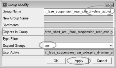
•在模型树栏,点击Group菜单,在模型树栏右击鼠标New Group,弹出创建组件对话框,如图11-22所示;
•Group Name:driveline_active;

图11-22 驱动轴显示组件对话框
•Object In Group(显示组件包括的部件、几何体、约束等对象):顺序输入①~ 对象如下信息所示。
① ._fsae_suspension_rear_axle.gel_drive_shaft;
② ._fsae_suspension_rear_axle.ger_drive_shaft;
③ ._fsae_suspension_rear_axle.gel_tripot;
④ ._fsae_suspension_rear_axle.ger_tripot;
⑤ ._fsae_suspension_rear_axle.ground.cfl_drive_shaft_otr;
⑥ ._fsae_suspension_rear_axle.ground.cfr_drive_shaft_otr;
⑦ ._fsae_suspension_rear_axle.ground.cfl_drive_shaft_inr;
⑧ ._fsae_suspension_rear_axle.ground.cfr_drive_shaft_inr;
⑨ ._fsae_suspension_rear_axle.mtl_tripot_to_differential;
⑩ ._fsae_suspension_rear_axle.mtr_tripot_to_differential;
 ._fsae_suspension_rear_axle.jolcon_drive_sft_int_jt;
 ._fsae_suspension_rear_axle.jorcon_drive_sft_int_jt;
 ._fsae_suspension_rear_axle.jolcon_drive_sft_otr;
 ._fsae_suspension_rear_axle.jorcon_drive_sft_otr;
 ._fsae_suspension_rear_axle.joltra_tripot_to_differential;
 ._fsae_suspension_rear_axle.jortra_tripot_to_differential;
 ._fsae_suspension_rear_axle.gel_drive_shaft.gralin_drive_shaft;
 ._fsae_suspension_rear_axle.gel_drive_shaft.graell_otr_cv_housing;
 ._fsae_suspension_rear_axle.gel_drive_shaft.graell_tripot_housing;
 ._fsae_suspension_rear_axle.gel_tripot.gracyl_tripot_housing_extention;
 ._fsae_suspension_rear_axle.ger_drive_shaft.gralin_drive_shaft;
 ._fsae_suspension_rear_axle.ger_drive_shaft.graell_otr_cv_housing;(https://www.chuimin.cn)
 ._fsae_suspension_rear_axle.ger_drive_shaft.graell_tripot_housing;
 ._fsae_suspension_rear_axle.ger_tripot.gracyl_tripot_housing_extention;
 ._fsae_suspension_rear_axle.mtl_fixed_2;
 ._fsae_suspension_rear_axle.mtr_fixed_2。
•Expr Active:(._fsae_suspension_rear_axle.phs_driveline_active || ._fsae_suspension_rear_axle.model_class == "template" ? 1:0);
•单击Apply,完成组件driveline_active的创建;
•Group Name:driveline_inactive;
•Expr Active:( ! ._fsae_suspension_rear_axle.phs_driveline_active || ._fsae_suspension_rear_axle.model_class == "template" ? 1:0);
•单击OK,完成组件driveline_inactive的创建。
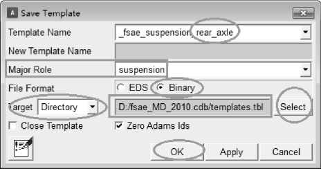
•单击File > Save As命令,弹出保存模板对话框,如图11-23所示;
•Major Role(主特征):suspension;;
•File Format:Binary;
•Target:Directory
•单击Select,选择存储路径为D:/fsae_MD_2010.cdb/templates.tbl;
•单击OK,完成推杆式悬架模型模板._fsae_suspension_rear_axle的保存。

图11-23 推杆式悬架模型保存
(推杆式悬架子系统)
•按F9,把专家模板转换到标准模式,单击File > New > Suspension命令,弹出子系统对话框,如图11-24所示;
•Subsystem Name(系统名称):fsae_suspension_rear_axle;
•Minor Role(副特征):rear(指悬架为后悬架);
•Template Name(模板路径):mdids://FASE/templates.tbl/_fsae_suspension_rear_axle.tpl;
•单击OK,完成推杆式悬架子系统fsae_suspension_rear_axle的创建。

图11-24 推杆式悬架子系统创建对话框
相关文章

单击Bodies > Construction > Geometry Point创建硬点;Add to Ground;Don't Attach;右击鼠标,弹出硬点位置对话框参考如图9-2所示;硬点位置输入2 000,-150,325;单击Apply,完成硬点创建;右击硬点,选择Rename,重名为hub_rear_l;单击Bodies > Construction > Geometry Point......
2025-09-30

板簧的初始几何轮廓是通过平展的板簧的弯曲角度或者高度完成定义。初始几何生成器根据输入的参数,会为每片板簧生成一组平展的梁单元,然后在弧高的测量点位置加上驱动,运行准静态分析后,平展的板簧可以变形为确定的孤高状态,即板簧前端与后端的完全形状,变形后板簧上表面内侧形状为初始几何轮廓。具体板簧初始几何尺寸设置如图2-2所示。图2-4板簧连接对话框......
2025-09-30

钢板弹簧是一种比较特殊的弹簧。鉴于这些优点,商用货车、农用车辆以及一些特种车辆仍在使用板簧。板簧在研究过程中主要采用三段梁法、Beam梁法,有限元模态法。离散Beam梁法采用无质量的柔性梁把离散刚体连接起来,Beam梁参数根据钢板弹簧界面形状与材料参数得出各片簧之间的接触。离散梁法建立的钢板弹簧与实际板簧模型接近,其精度较高,计算经济性好,综合特性优良。图2-1板簧模型学习目标 板簧工具箱介绍。......
2025-09-30

单击Build > Construction Frame > New命令,结构框创建如图4-7所示;Construction Frame(结构框名称):crankshaft_reference;Location Dependency:Delta location from coordinate;图4-7结构框Coordinate Reference (参考坐标):._my_engine.grou......
2025-09-30

基于ADAMS整车环境模式下对制动系统进行研究可以取得较好的效果,其仿真结果可以作为设计制造制动器的依据,同时也可以验证不同制动控制算法的优劣。ADAMS/CAR中商用牵引车三轴系制动系统中(6×4)制动力矩函及牵引车附加拖车(5轴系)制动力矩函同上述相同,其制动系统模型如图7-2~图7-3所示。图7-2商用车制动系统模型图7-3商用车附带拖车制动系统模型......
2025-09-30

图8-8单线移仿真设置对话框仿真正确且结束后,查看车身的垂向加速度与侧向加速度,根据数据评估FSAE整车运行状态及稳定性。图8-9车身垂向加速度图8-10车身侧向加速度从仿真结果中可以看出,FSAE赛车在经过减速度瞬间,车身垂直方向产生剧烈振动,最大值接近2.5g;车身侧向加速度最大值接近1.5g,在负方向伴有高频振动趋势。单线移仿真注意事项:单线移在仿真时可能出现错误,但能仿真完成。......
2025-09-30
相关推荐