钢板弹簧是一种比较特殊的弹簧。鉴于这些优点,商用货车、农用车辆以及一些特种车辆仍在使用板簧。板簧在研究过程中主要采用三段梁法、Beam梁法,有限元模态法。离散Beam梁法采用无质量的柔性梁把离散刚体连接起来,Beam梁参数根据钢板弹簧界面形状与材料参数得出各片簧之间的接触。离散梁法建立的钢板弹簧与实际板簧模型接近,其精度较高,计算经济性好,综合特性优良。图2-1板簧模型学习目标 板簧工具箱介绍。......
2025-09-30
(1)前轴差速器参考硬点、结构框。
•启动ADAMS/DRIVERLINE;
•单击File > New命令,弹出建模对话框,如图6-2所示;

图6-2 传动系统模板
•Template Name:my_AWD_driveline;
•Major Role:driveline;
•单击OK,完成驱动轴模板建立。
•单击Build > Hardpoint > New命令,弹出创建硬点对话框,如图6-3所示;
•Hardpoint Name:front_diff_ref;
•Type:single;
•Location:1 500,-200.0,225.0;
•单击OK,完成._my_AWD_driveline.ground.hps_front_diff_ref硬点的创建。

图6-3 前差速器参考点
•单击Build > Construction Frame > New命令,如图6-4所示;
•Construction Frame(结构框名称):front_diff_ref;
•Location Dependency:Delta location from coordinate;
•Coordinate Reference (参考坐标):._my_AWD_driveline.ground.hps_front_diff_ref;
•Location:0,0,0;
•Location in:local;
•Orientation Dependency:User entered values;
•Orient using:Euler Angles;
•Euler Angles:0,90,0;(https://www.chuimin.cn)

图6-4 前差速器结构框——front_diff_ref
•单击OK,完成._my_AWD_driveline.ground.cfs_front_diff_ref结构框的创建。
(2)前轴差速器整体部件。
•单击Driveline Components > COMPLEX COMPONENTS > Entire Differential Unit命令,如图6-5所示;

图6-5 前差速器部件
•Differential Center Reference:Delta location from coordinate;
•Differential Name(变速器名称):front;
•Side Gear Radius(行星齿轮左右两侧齿轮半径):40;
•Pinion Gear Radius(行星齿轮前后两侧齿轮半径):30;
•Ring Gear Outer Radius(从动齿轮外径):120;
•Ring Gear Inner Radius(从动齿轮内径):60;
•Ring Gear Offset(从动齿轮偏移量):-50;
•Ring Gear Geometry(准双曲面齿轮):Hypoid;
•Mass:10;
•Ixx:1E4;
•Iyy:1E4;
•Izz:1E4;
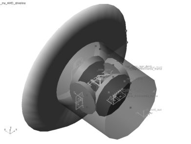
•单击OK,完成前差速器整体部件的创建,如图6-6所示。

图6-6 前差速器
相关文章

钢板弹簧是一种比较特殊的弹簧。鉴于这些优点,商用货车、农用车辆以及一些特种车辆仍在使用板簧。板簧在研究过程中主要采用三段梁法、Beam梁法,有限元模态法。离散Beam梁法采用无质量的柔性梁把离散刚体连接起来,Beam梁参数根据钢板弹簧界面形状与材料参数得出各片簧之间的接触。离散梁法建立的钢板弹簧与实际板簧模型接近,其精度较高,计算经济性好,综合特性优良。图2-1板簧模型学习目标 板簧工具箱介绍。......
2025-09-30

单击Build > Construction Frame > New命令,结构框创建如图4-7所示;Construction Frame(结构框名称):crankshaft_reference;Location Dependency:Delta location from coordinate;图4-7结构框Coordinate Reference (参考坐标):._my_engine.grou......
2025-09-30

与此同时系统自动建立两个输出通信器:col[r]_toe_angle、col[r]_camber_angle。图1-21悬架参数单击Build > Construction Frame > New命令,弹出创建结构框,如图1-22所示;Construction Frame:wheel_center;Coordinate Reference:_fsae_suspension_rear_axle.ground.hpl_wheel_center;Location:0,0,0;Location in:local;Orientation Dependency:User-entered values;Variable Type:Parameter Variable;Toe Parameter Values:._fsae_suspension_rear_axle.pvl_toe_angle;Camber Parameter Values:._fsae_suspension_rear_axle.pvl_camber_angle;单击OK,完成._fsae_suspension_rear_axle.ground.cfl_wheel_center结构框的创建。......
2025-09-30

图4-28速度保持仿真提交运算后命令窗口提示保持仿真并不能提交,经分析发现问题在于发动机子系统,发动机的动力元设置存在问题,命令窗口信息如下。图4-29动力元素修改设置V12_engine发动机特性曲线图,此问题可以通过实验数据编写真实的发动机参数,此处为共享数据库中发动机模板数据:修改完成后,速度保持仿真设置不变,重新提交,整车顺利完成仿真,切换到后处理模块,计算结果如图4-30~图4-38所示。......
2025-09-30

单击Build > Part > General Part > New命令,弹出创建部件对话参考如图4-5所示;General Part输入flywheel_2;Location Dependency:Delta location from coordinate;Coordinate Reference (参考坐标):._my_engine.ground.hps_crankshaft_refere......
2025-09-30

单击Build > Attachments > Joint > New命令,弹出创约束件对话框,如图3-14所示;Joint Name:p1;I Part:._my_leaf_4.nrl_1_beam1;J Part:._my_leaf_4.mts_leafspring_to_body;Joint Type:revolute;Active(激活):kinematic mode;Location Dependency:Delta location from coordinate;图3-14刚性约束对话框—revoluteCoordinate Reference:._my_leaf_4.ground.hpl_p1;Location:0,0,0;Location in:local;Orientation Dependency:Delta orientation from coordinate;Construction Frame:._my_leaf_4.ground.cfl_p1;单击Apply,完成约束副._my_leaf_4.jklrev_p1的创建。部件shackle与安装件leafspring_to_body之间revolute约束。部件rear_axle与nrl_4_beam4之间fixed约束。......
2025-09-30
相关推荐